Cluster Network
Concepts
Cluster Network
Available as of v1.1.0
In Harvester v1.1.0, we introduced a new concept called cluster network for traffic isolation.
The following diagram describes a typical network architecture that separates data-center (DC) traffic from out-of-band (OOB) traffic.
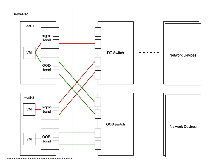
We abstract the sum of devices, links, and configurations on a traffic-isolated forwarding path on Harvester as a cluster network.
In the above case, there will be two cluster networks corresponding to two traffic-isolated forwarding paths.
Network Configuration
Specifications including network devices of the Harvester hosts can be different. To be compatible with such a heterogeneous cluster, we designed the network configuration.
Network configuration only works under a certain cluster network. Each network configuration corresponds to a set of hosts with uniform network specifications. Therefore, multiple network configurations are required for a cluster network on non-uniform hosts.
VM Network
A VM network is an interface in a virtual machine that connects to the host network. As with a network configuration, every network except the built-in management network must be under a cluster network.
Harvester supports adding multiple networks to one VM. If a network's cluster network is not enabled on some hosts, the VM that owns this network will not be scheduled to those hosts.
Please refer to network part for more details about networks.
Relationship Between Cluster Network, Network Config, VM Network
The following diagram shows the relationship between a cluster network, a network config, and a VM network.
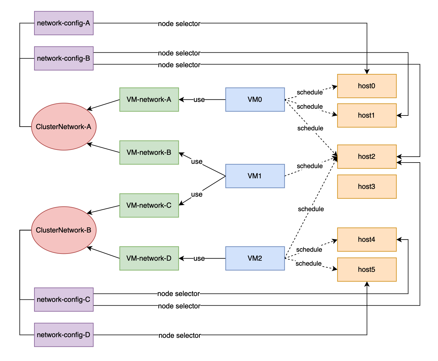
All Network Configs and VM Networks are grouped under a cluster network.
- A label can be assigned to each host to categorize hosts based on their network specifications.
- A network config can be added for each group of hosts using a node selector.
For example, in the diagram above, the hosts in ClusterNetwork-A are divided into three groups as follows:
- The first group includes host0, which corresponds to
network-config-A. - The second group includes host1 and host2, which correspond to
network-config-B. - The third group includes the remaining hosts (host3, host4, and host5), which do not have any related network config and therefore do not belong to
ClusterNetwork-A.
The cluster network is only effective on hosts that are covered by the network configuration. A VM using a VM network under a specific cluster network can only be scheduled on a host where the cluster network is active.
In the diagram above, we can see that:
ClusterNetwork-Ais active on host0, host1, and host2.VM0usesVM-network-A, so it can be scheduled on any of these hosts.VM1uses bothVM-network-BandVM-network-C, so it can only be scheduled on host2 where bothClusterNetwork-AandClusterNetwork-Bare active.VM0,VM1, andVM2cannot run on host3 where the two cluster networks are inactive.
Overall, this diagram provides a clear visualization of the relationship between cluster networks, network configurations, and VM networks, as well as how they impact VM scheduling on hosts.
Cluster Network Details
Cluster networks are traffic-isolated forwarding paths for transmission of network traffic within a Harvester cluster.
A cluster network called mgmt is automatically created when a Harvester cluster is deployed. You can also create custom cluster networks that can be dedicated to virtual machine traffic.
Built-in Cluster Network
When a Harvester cluster is deployed, a cluster network named mgmt is automatically created for intra-cluster communications. mgmt consists of the same bridge, bond, and NICs as the external infrastructure network to which each Harvester host attaches with management NICs. Because of this design, mgmt also allows virtual machines to be accessed from the external infrastructure network for cluster management purposes.
mgmt does not require a network configuration and is always enabled on all hosts. You cannot disable and delete mgmt.
Certain ARP settings can break cluster communications. With arp_ignore=2, for example, replies are sent only if the sender IP address is in the same subnet as the target IP address for which the MAC address is requested. This is not the case in a Harvester cluster, so using arp_ignore=2 on all interfaces results in failed connectivity checks and prevents Longhorn pods (specifically, backing-image and instance-manager) from transitioning to the Ready state. Volumes cannot be attached to virtual machines if these Longhorn pods are not ready.
Custom Cluster Network
If more than one network interface is attached to each host, you can create custom cluster networks for better traffic isolation. Each cluster network must have at least one network configuration with a defined scope and bonding mode.
The witness node is generally not involved in the custom cluster network.
Configuration
Create a New Cluster Network
To simplify cluster maintenance, create one network configuration for each node or group of nodes. Without dedicated network configurations, certain maintenance tasks (for example, replacing old NICs with NICs in different slots) will require you to stop and/or migrate the affected virtual machines before updating the network configuration.
-
Ensure that the hardware requirements are met.
-
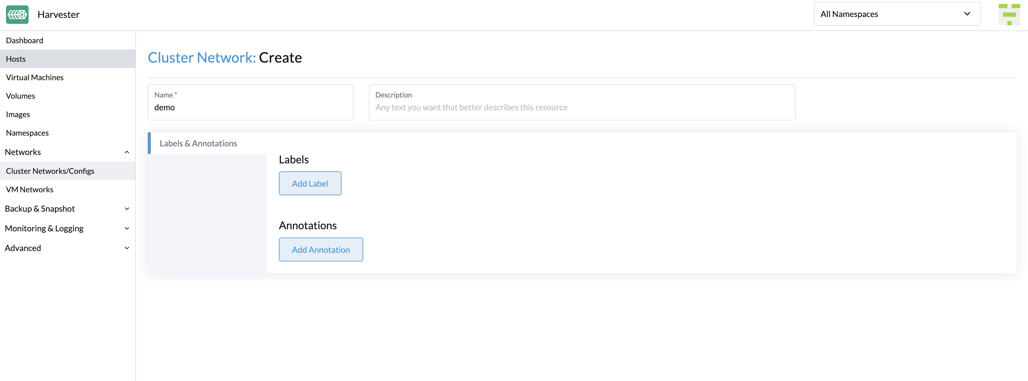
Go to Networks > ClusterNetworks/Configs, and then click Create.
-
Specify a name for the cluster network.
-
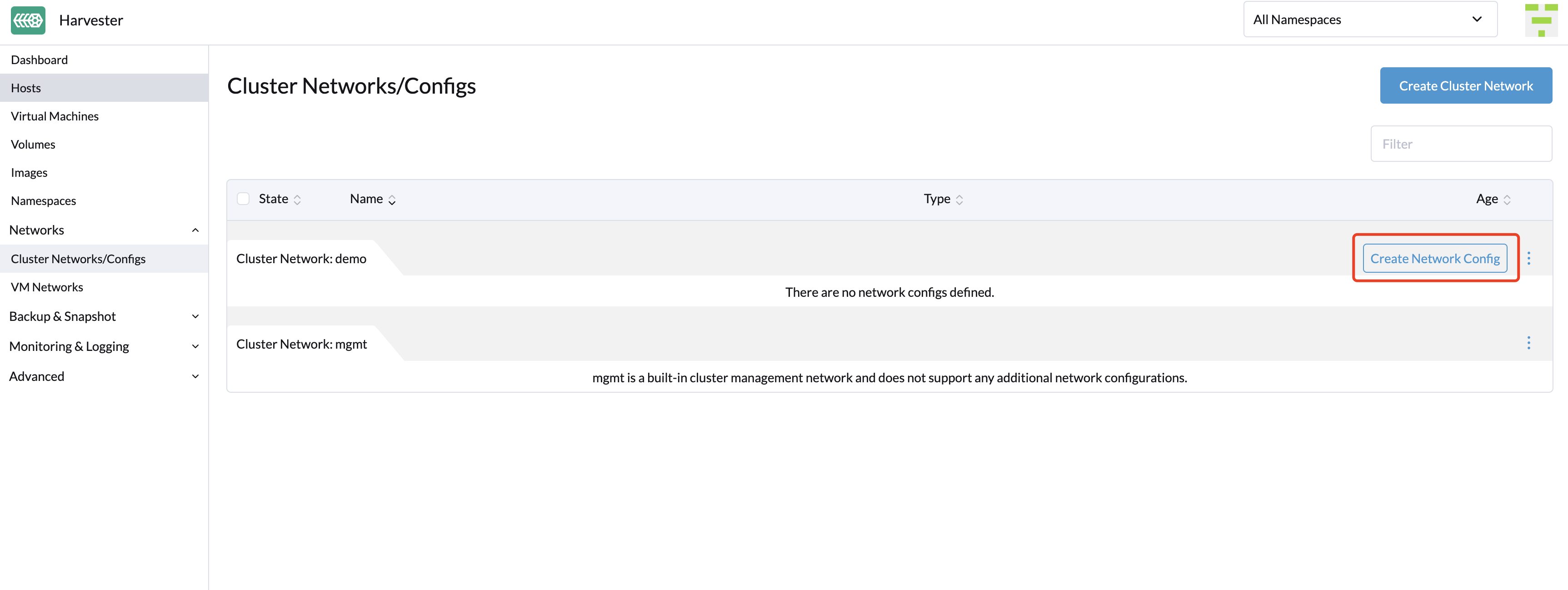
On the ClusterNetworks/Configs screen, click the Create Network Config button of the cluster network you created.
-
On the Network Config:Create screen, specify a name for the configuration.
-
On the Node Selector tab, select the method for defining the scope of this specific network configuration.
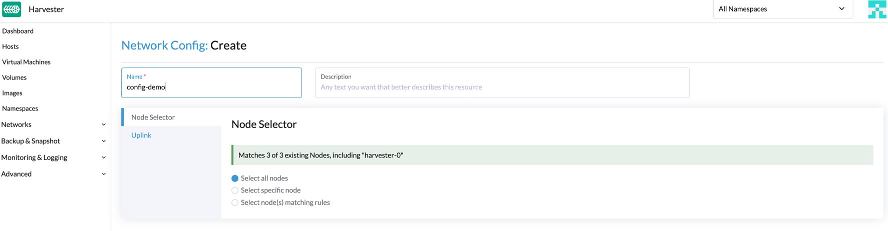 note
note- The method Select all nodes works only when all nodes use the exact same dedicated NICs for this specific custom cluster network. In other situations (for example, when the cluster has a witness node), you must select either of the remaining methods.
- If you want the configuration to apply to nodes that are not covered by the selected method, you must create another network configuration.
-
On the Uplink tab, configure the following settings:
- NICs: The list contains NICs that are common to all selected nodes. NICs that cannot be selected are unavailable on one or more nodes and must be configured. Once troubleshooting is completed, refresh the screen and verify that the NICs can be selected.
- Bond Options: The default bonding mode is active-backup.
- Attributes: You must use the same MTU across all network configurations of a custom cluster network. If you do not specify an MTU, the default value 1500 is used.
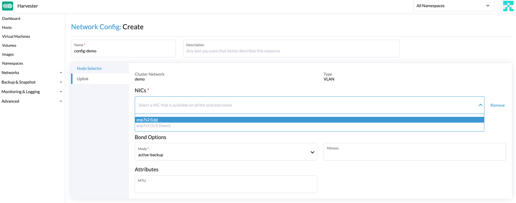
-
Click Save.
Change a Network Configuration
Changes to existing network configurations may affect Harvester virtual machines and workloads, and external devices such as switches and routers. For more information, see Network Topology.
You must stop all affected virtual machines before changing a network configuration.
General Changes
-
Locate the target cluster network and network configuration.
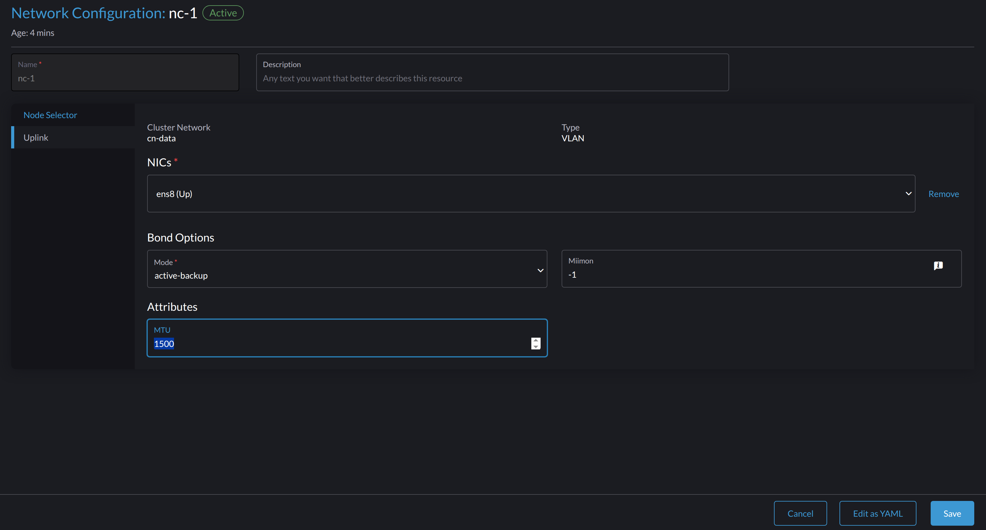
In the following example, the cluster network is
cn-dataand the network configuration isnc-1.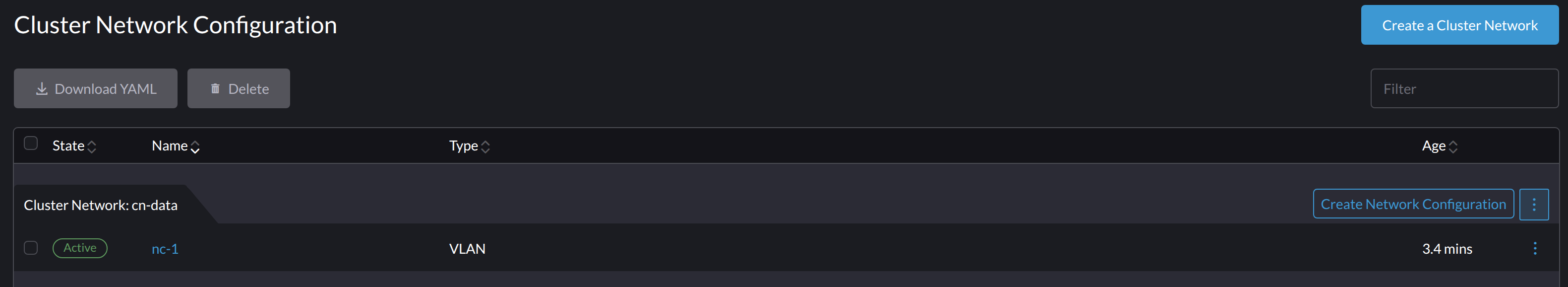
-
Select ⋮ > Edit Config, and then change the relevant fields.
- Node Selector tab:
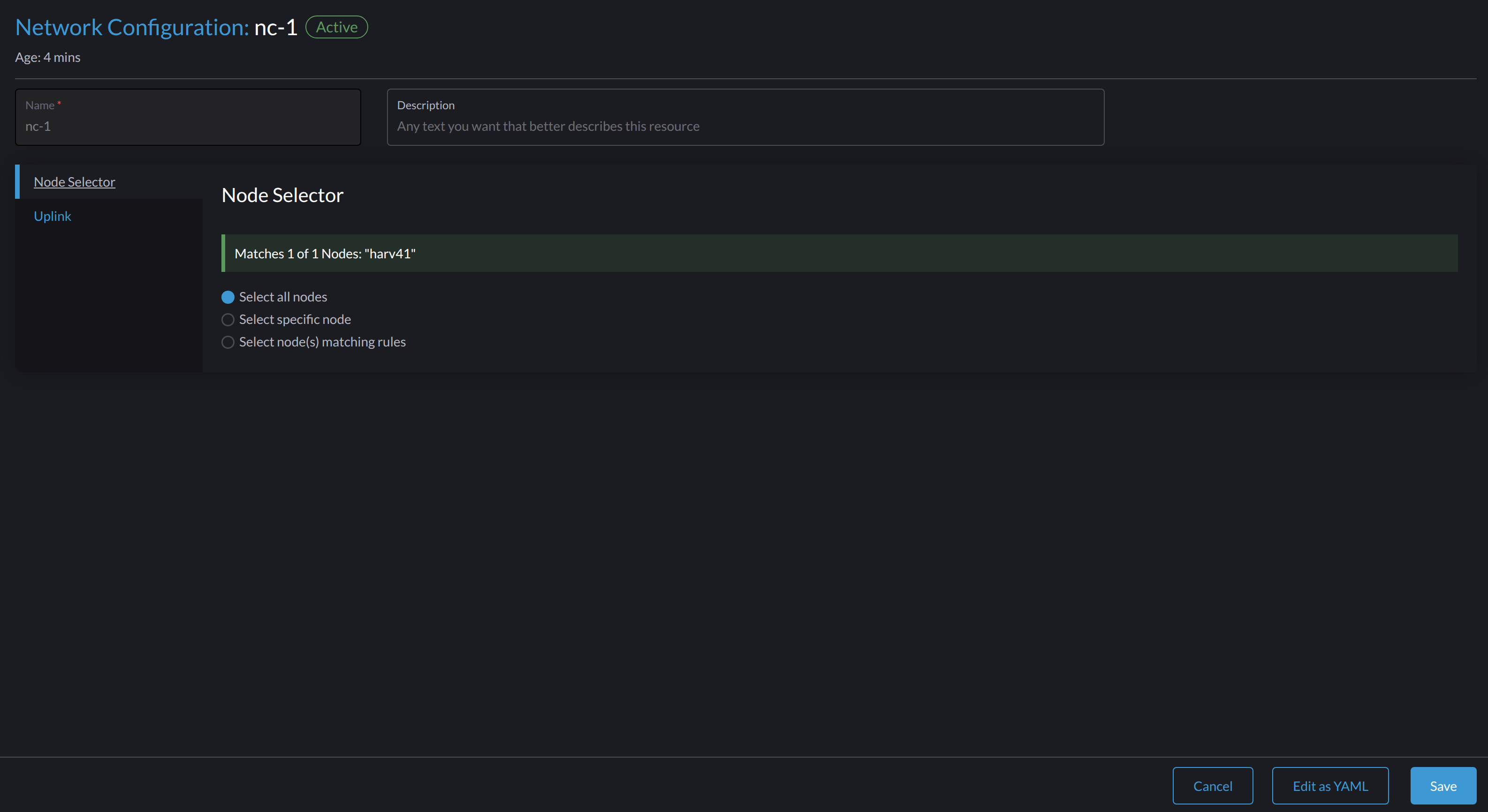
- Uplink tab:
 important
You must use the same values for the Bond Options and Attributes fields in all network configurations of a custom cluster network.
-
Click Save.
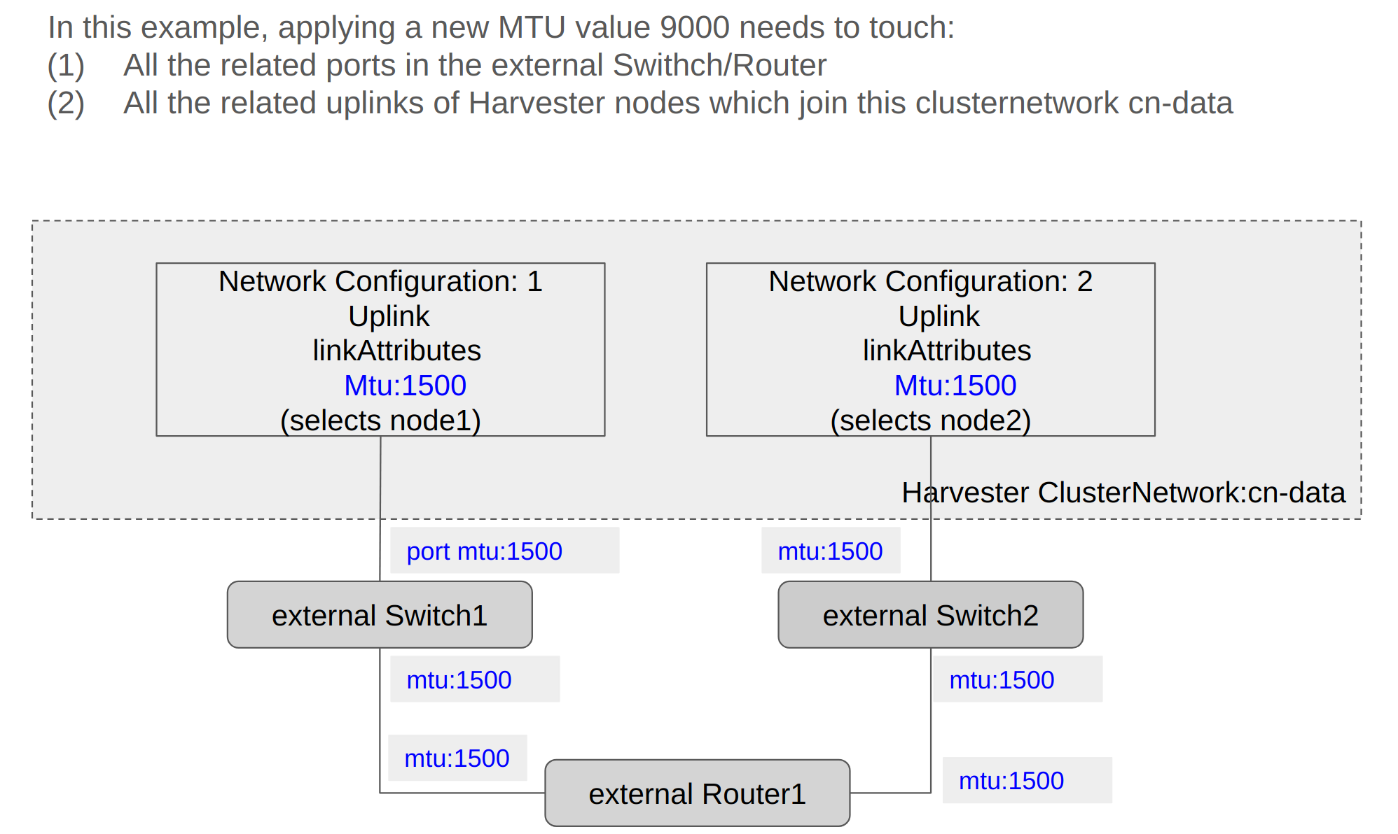
The following sections outline the steps you must perform to change the MTU of a network configuration. The sample cluster network used in these sections has cn-data that was built with a MTU value 1500 and is intended to be changed with value 9000.
Change the MTU of a Network Configuration with No Attached Storage Network
In this scenario, the storage network is neither enabled nor attached to the target cluster network.
- The MTU affects Harvester nodes and networking devices such as switches and routers. Careful planning and testing are required to ensure that changing the MTU does not adversely affect the system. For more information, see Network Topology.
- You must use the same MTU across all network configurations of a custom cluster network. You must also manually update the MTU on existing virtual machine networks.
- Cluster operations are interrupted during the configuration change.
- The information in this section does not apply to the built-in
mgmtcluster network.
If you must change the MTU, perform the following steps:
-
Stop all virtual machines that are attached to the target cluster network.
You can check this using the VM network and any secondary networks you may have used. Harvester does not allow you to change the MTU when any of the connected virtual machines are still running.
-
Check the network configurations of the target cluster network.
If multiple network configurations exist, record the node selector for each and remove configurations until only one remains.
-
Change the MTU of the remaining network configuration.
importantYou must also change the MTU on the peer external switch or router.
-
Verify that the MTU was changed using the Linux
ip linkcommand. If the network configuration selects multiple Harvester nodes, run the command on each node.The output must show the new MTU of the related
*-brdevice and the stateUP. In the following example, the device iscn-data-brand the new MTU is9000.Harvester node $ ip link show dev cn-data-br
|new MTU| |state UP|
3: cn-data-br: <BROADCAST,MULTICAST,UP,LOWER_UP> mtu 9000 qdisc noqueue state UP mode DEFAULT group default qlen 1000
link/ether 52:54:00:6e:5c:2a brd ff:ff:ff:ff:ff:ffnoteWhen the state is
UNKNOWN, it is likely that the MTU values on Harvester and the external switch or router do not match. -
Test the new MTU on Harvester nodes using commands such as
ping. You must send the messages to a Harvester node with the new MTU or a node with an external IP.In the following example, the network is
cn-data, the CIDR is192.168.100.0/24, and the gateway is192.168.100.1.-
Set the IP
192.168.100.100on the bridge device.$ ip addr add dev cn-data-br 192.168.100.100/24 -
Add a route for the destination IP (for example,
8.8.8.8) via the gateway.$ ip route add 8.8.8.8 via 192.168.100.1 dev cn-data-br -
Ping the destination IP from the new IP
192.168.100.100.$ ping 8.8.8.8 -I 192.168.100.100
PING 8.8.8.8 (8.8.8.8) from 192.168.100.100 : 56(84) bytes of data.
64 bytes from 8.8.8.8: icmp_seq=1 ttl=59 time=8.52 ms
64 bytes from 8.8.8.8: icmp_seq=2 ttl=59 time=8.90 ms
... -
Ping the destination IP with a different packet size to validate the new MTU.
$ ping 8.8.8.8 -s 8800 -I 192.168.100.100

PING 8.8.8.8 (8.8.8.8) from 192.168.100.100 : 8800(8828) bytes of data

The param `-s` specify the ping packet size, which can test if the new MTU really works -
Remove the route that you used for testing.
$ ip route delete 8.8.8.8 via 192.168.100.1 dev cn-data-br -
Remove the IP that you used for testing.
$ ip addr delete 192.168.100.100/24 dev cn-data-br
-
-
Add back the network configurations that you removed.
importantYou must change the MTU in each one, and verify that the new MTU was applied.
-
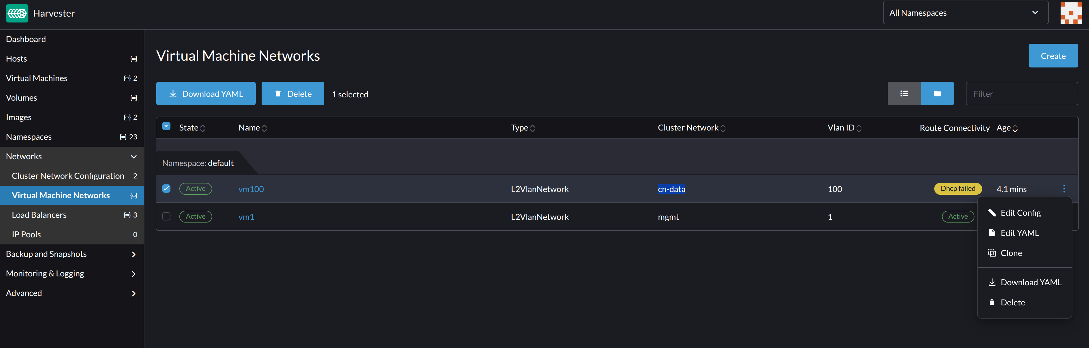
Edit the YAML of all virtual machine networks that are attached to the target cluster network.
On the Harvester UI Virtual Machine Networks screen, perform the following steps for each attached network:
-
Select ⋮ > Edit YAML.
-
Change the MTU.
-
Click Save.
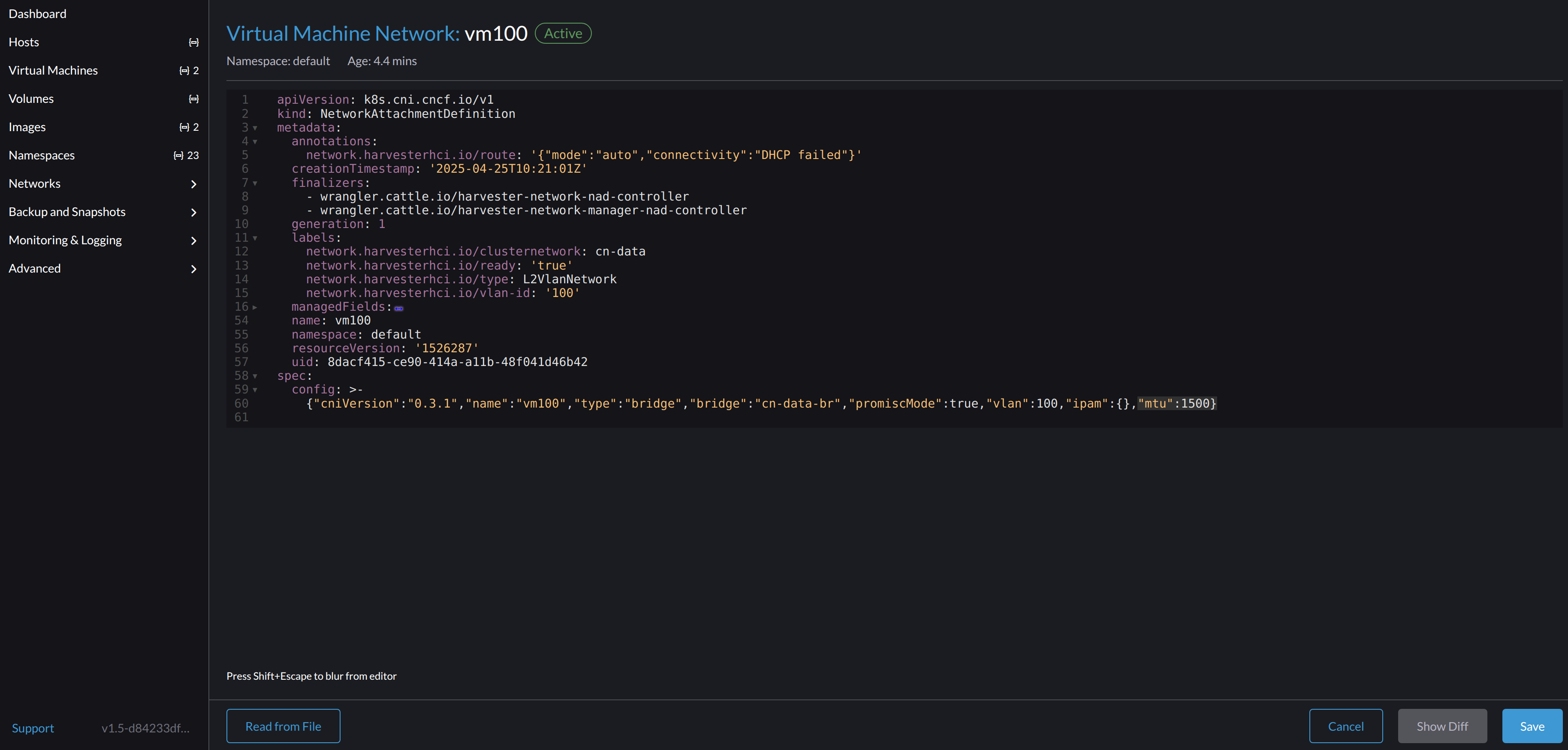
You can also use
kubectlto change the MTU. In the following example, the network name isvm100. To edit the YAML of this network, run the commandkubectl edit NetworkAttachmentDefinition.k8s.cni.cncf.io vm100.apiVersion: k8s.cni.cncf.io/v1
kind: NetworkAttachmentDefinition
metadata:
annotations:
network.harvesterhci.io/route: '{"mode":"auto","serverIPAddr":"","cidr":"","gateway":""}'
creationTimestamp: '2025-04-25T10:21:01Z'
finalizers:
- wrangler.cattle.io/harvester-network-nad-controller
- wrangler.cattle.io/harvester-network-manager-nad-controller
generation: 1
labels:
network.harvesterhci.io/clusternetwork: cn-data
network.harvesterhci.io/ready: 'true'
network.harvesterhci.io/type: L2VlanNetwork
network.harvesterhci.io/vlan-id: '100'
name: vm100
namespace: default
resourceVersion: '1525839'
uid: 8dacf415-ce90-414a-a11b-48f041d46b42
spec:
config: >-
{"cniVersion":"0.3.1","name":"vm100","type":"bridge","bridge":"cn-data-br","promiscMode":true,"vlan":100,"ipam":{},"mtu":1500} -
-
Start all virtual machines that are attached to the target cluster network.
The virtual machines should have inherited the new MTU. You can verify this in the guest operating system using the commands
ip linkandping 8.8.8.8 -s 8800. -
Verify that the virtual machine workloads are running normally.
Harvester cannot be held responsible for any damage or loss of data that may occur when the MTU value is changed.
Change the MTU of a Network Configuration with an Attached Storage Network
In this scenario, the storage network is enabled and attached to the target cluster network.
The storage network is used by driver.longhorn.io, which is Harvester's default CSI driver. Longhorn is responsible for provisioning root volumes, so changing the MTU affects all virtual machines.
- The MTU affects Harvester nodes and networking devices such as switches and routers. Careful planning and testing are required to ensure that changing the MTU does not adversely affect the system. For more information, see Network Topology.
- You must use the same MTU across all network configurations of a custom cluster network. You must also manually update the MTU on existing virtual machine networks.
- All cluster operations are interrupted during the configuration change.
- The information in this section does not apply to the built-in
mgmtcluster network.
If you must change the MTU, perform the following steps:
-
Stop all virtual machines.
-
Disable the storage network.
Allow some time for the setting to be disabled, and then verify that the change was applied.
-
Check the network configurations of the target cluster network.
If multiple network configurations exist, record the node selector for each and remove configurations until only one remains.
-
Change the MTU of the remaining network configuration.
importantYou must also change the MTU on the peer external switch or router.
-
Verify that the MTU was changed using the Linux
ip linkcommand.If the network configuration selects multiple Harvester nodes, run the command on each node.
The output must show the new MTU of the related
*-brdevice and the stateUP. In the following example, the device iscn-data-brand the new MTU is9000.Harvester node $ ip link show dev cn-data-br
|new MTU| |state UP|
3: cn-data-br: <BROADCAST,MULTICAST,UP,LOWER_UP> mtu 9000 qdisc noqueue state UP mode DEFAULT group default qlen 1000
link/ether 52:54:00:6e:5c:2a brd ff:ff:ff:ff:ff:ffnoteWhen the state is
UNKNOWN, it is likely that the MTU values on Harvester and the external switch or router do not match. -
Test the new MTU on Harvester nodes using commands such as
ping. You must send the messages to a Harvester node with the new MTU or to a node with an external IP.In the following example, the network is
cn-data, the CIDR is192.168.100.0/24, and the gateway is192.168.100.1.-
Set the IP
192.168.100.100on the bridge device.$ ip addr add dev cn-data-br 192.168.100.100/24 -
Add a route for the destination IP (for example,
8.8.8.8) via the gateway.$ ip route add 8.8.8.8 via 192.168.100.1 dev cn-data-br -
Ping the destination IP from the new IP
192.168.100.100.$ ping 8.8.8.8 -I 192.168.100.100
PING 8.8.8.8 (8.8.8.8) from 192.168.100.100 : 56(84) bytes of data.
64 bytes from 8.8.8.8: icmp_seq=1 ttl=59 time=8.52 ms
64 bytes from 8.8.8.8: icmp_seq=2 ttl=59 time=8.90 ms
... -
Ping the destination IP with a different packet size to validate the new MTU.
$ ping 8.8.8.8 -s 8800 -I 192.168.100.100

PING 8.8.8.8 (8.8.8.8) from 192.168.100.100 : 8800(8828) bytes of data

The param `-s` specify the ping packet size, which can test if the new MTU really works -
Remove the route that you used for testing.
$ ip route delete 8.8.8.8 via 192.168.100.1 dev cn-data-br -
Remove the IP that you used for testing.
$ ip addr delete 192.168.100.100/24 dev cn-data-br
-
-
Add back the network configurations that you removed.
importantYou must change the MTU in each one, and verify that the new MTU was applied.
-
Enable and configure the Harvester storage network setting, ensuring that the prerequisites are met.
-
Allow some time for the setting to be enabled, and then verify that the change was applied.
-
Edit the YAML of all virtual machine networks that are attached to the target cluster network.
On the Harvester UI Virtual Machine Networks screen, perform the following steps for each attached network:
-
Select ⋮ > Edit YAML.
-
Change the MTU.
-
Click Save.
You can also use
kubectlto change the MTU. In the following example, the network name isvm100. To edit the YAML of this network, run the commandkubectl edit NetworkAttachmentDefinition.k8s.cni.cncf.io vm100.apiVersion: k8s.cni.cncf.io/v1
kind: NetworkAttachmentDefinition
metadata:
annotations:
network.harvesterhci.io/route: '{"mode":"auto","serverIPAddr":"","cidr":"","gateway":""}'
creationTimestamp: '2025-04-25T10:21:01Z'
finalizers:
- wrangler.cattle.io/harvester-network-nad-controller
- wrangler.cattle.io/harvester-network-manager-nad-controller
generation: 1
labels:
network.harvesterhci.io/clusternetwork: cn-data
network.harvesterhci.io/ready: 'true'
network.harvesterhci.io/type: L2VlanNetwork
network.harvesterhci.io/vlan-id: '100'
name: vm100
namespace: default
resourceVersion: '1525839'
uid: 8dacf415-ce90-414a-a11b-48f041d46b42
spec:
config: >-
{"cniVersion":"0.3.1","name":"vm100","type":"bridge","bridge":"cn-data-br","promiscMode":true,"vlan":100,"ipam":{},"mtu":1500} -
-
Start all virtual machines that are attached to the target cluster network.
The virtual machines should have inherited the new MTU. You can verify this from the guest operating system using the Linux
ip linkcommand andping 8.8.8.8 -s 8800command. -
Verify that the virtual machine workloads are running normally.
Harvester cannot be held responsible for any damage or loss of data that may occur when the MTU value is changed.