Harvester Network Deep Dive
The network topology below reveals how we implement the Harvester network.
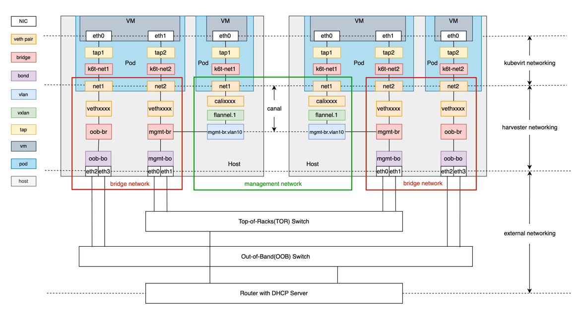
The diagram contains the built-in cluster network mgmt and a custom cluster network called oob.
As shown above, the Harvester network primarily focuses on OSI model layer 2. We leverage Linux network devices and protocols to construct traffic paths for the communication between VM to VM, VM to host, and VM to external network devices.
The Harvester network is composed of three layers, including:
KubeVirt networking layer
Harvester networking layer
external networking layer
KubeVirt Networking
The general purpose of KubeVirt is to run VM inside the Kubernetes pod. The KubeVirt network builds the network path between the pod and VM. Please refer to the KubeVirt official document for more details.
Harvester Networking
Harvester networking is designed to build the network path between pods and the host network. It implements a management network, VLAN networks and untagged networks. We can refer to the last two networks as bridge networks, because bridge plays a vital role in their implementation.
Bridge Network
We leverage multus CNI and bridge CNI to implement the bridge network.
Multus CNI is a Container Network Interface (CNI) plugin for Kubernetes that can attach multiple network interfaces to a pod. Its capability allows a VM to have one NIC for the management network and multiple NICs for the bridge network.
Using the bridge CNI, the VM pod will be plugged into the L2 bridge specified in the Network Attachment Definition config.
# Example 1
{
    "cniVersion": "0.3.1",
    "name": "vlan100",
    "type": "bridge",
    "bridge": "mgmt-br",
    "promiscMode": true,
    "vlan": 100,
}
# Example 2
{
"cniVersion": "0.3.1",
"name": "untagged-network",
"type": "bridge",
"bridge": "oob-br",
"promiscMode": true,
"ipam": {}
}Example 1 is a typical VLAN configuration with VLAN ID 100, while Example 2 is an untagged network configuration with no VLAN ID. The VM pod configured using Example 1 will be plugged into the bridge
mgmt-br, while the VM pod using Example 2 will be plugged into the bridgeoob-br.To achieve high availability and fault tolerance, a bond device where the real NICs are bound is created to serve as the uplink of the bridge. By default, this bond device will allow the target tagged traffic/packets to pass through.
harvester-0:/home/rancher # bridge -c vlan show dev oob-bo
port       vlan ids
oob-bo     1 PVID Egress Untagged
           100
           200
The example above shows that the bond
oob-boallows packages with tag 1, 100 or 200.
Management Network
The management network is based on Canal.
It is worth mentioning that the Canal interface where the Harvester configures the node IP is the bridge mgmt-br or a VLAN sub-interface of mgmt-br. This design has two benefits:
- The built-in
mgmtcluster network supports both the management network and bridge network. - With the VLAN network interface, we can assign a VLAN ID to the management network.
As components of the mgmt cluster network, it's not allowed to delete or modify the bridge mgmt-br, the bond mgmt-bo and the VLAN device.
External Networking
External network devices typically refer to switches and DHCP servers. With a cluster network, we can group host NICs and connect them to different switches for traffic isolation. Below are some usage instructions.
To allow tagged packets to pass, you need to set the port type of the external switch or other devices (such as a DHCP server) to trunk or hybrid mode and allow the specified VLAN tag.
You need to configure link aggregation on the switch based on the bond mode of the peer host. Link aggregation can work in manual mode or LACP mode. The following lists the correspondence between bond mode and link aggregation mode.
Bond Mode Link Aggregation Mode mode 0(balance-rr) manual mode 1(active-backup) none mdoe 2(balance-oxr) manual mode 3(broadcast) manual mode 4(802.3ad) LACP mode 5(balance-tlb) none mode 6(balance-alb) none If you want VMs in a VLAN to be able to obtain IP addresses through the DHCP protocol, configure an IP pool for that VLAN in the DHCP server.